文章编号: 2096-3203(2022)01-0192-09 中图分类号: TM732
2. 可再生能源发电与并网技术教育部工程研究中心(新疆大学), 新疆维吾尔自治区 乌鲁木齐 830047
我国能源中心与负荷中心相距较远,直流输电系统因其大容量、远距离的特点而受到广泛关注[1]。但其结构复杂,仍然存在较多的问题,换相失败是直流系统逆变器的主要故障之一,国内外学者的研究多基于逆变侧交直交互关系展开[2-5]。文献[6-7]仿真分析了不同故障引起换相失败的特性,并指出故障不同时,换相失败的控制与保护特性不同。文献[8]分析了交流系统非对称故障时负序电压分量对换相失败准确判别的影响。文献[9]同时考虑了交流电压下降和直流电流上升对换相的影响,并通过不同过渡电阻进行了仿真验证。文献[10]基于换流方程推导了关断角表达式,指出交流系统非对称故障时,换流母线电压过零点前移会增大换相失败可能性。以上研究仅分析了受端交流系统故障对换相的影响,但故障后100 ms保护动作隔离故障[11]会导致系统再次受到冲击,可能导致换相失败。因此研究断路器跳闸对换相过程的影响具有重要意义。
文中针对受端单回线交直流系统,分析单相断路器跳闸对逆变器换相的影响。基于逆变侧交流线路发生单相高阻接地故障,推导断路器跳闸后换流母线电压表达式,分析换流母线电压特性,研究其对关断角的影响,并在PSCAD/EMTDC电磁暂态仿真软件平台搭建交直流仿真模型进行仿真验证。
1 换相失败及其影响因素交直流系统中,逆变侧交流线路故障后,换流母线电压跌落,因此作用在阀上的反向电压不能达到使其关断的要求,从而导致换相失败[12]。当关断角γ小于临界关断角γmin时,可认为换相失败[2]。γ的数学表达式为[10]:
| $ \gamma=\arccos \left(\frac{\sqrt{2} k_{\mathrm{I}} I_{\mathrm{d}} X_{\mathrm{CI}}}{N U_{\mathrm{LI}}}+\cos \beta\right)-\varphi $ | (1) |
式中:XCI为逆变侧换相电抗;ULI为换流母线电压;kI为换流变压器变比;β为触发超前角;N为6脉动换流器的个数;Id为直流电流;φ为换流母线电压过零点前移角,对称故障时为零。
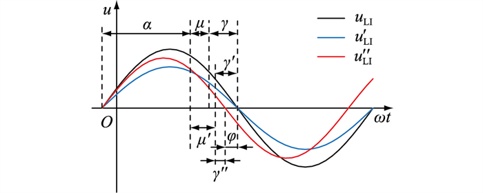
逆变侧交流线路发生故障时,换流母线电压简化波形如图 1所示[2]。
|
图 1 换流母线电压波形 Fig. 1 Voltage waveforms of commutator bus |
图 1中,uLI, u′ LI, u″ LI分别为换流母线正常运行、发生对称故障及非对称故障电压波形;α为触发角;μ, γ分别为正常运行时的换相角及关断角;μ′, γ′分别为对称故障时的换相角及关断角;γ″为非对称故障时的关断角。发生对称故障时,uLI幅值减小,μ增大为μ′, φ为0,γ减小为γ′[13];发生非对称故障时,uLI幅值降低,且φ增大,此时关断角受二者共同影响。
2 单相断路器跳闸对换相的影响交直流系统简化模型如图 2所示。

|
图 2 交直流系统简化模型 Fig. 2 AC/DC system simplified model |
图 2中,

|
图 3 交直流系统等效模型 Fig. 3 AC/DC system equivalent model |
图 3中,
正常运行时换流母线电压为:
| $ \left\{\begin{array}{l} \dot{U}_{M\text {ab }}=-\dot{A} \frac{\dot{K}_{1}}{Z_{\Sigma(1)}} \\ \dot{U}_{M\text {bc }}=(\dot{A}-\dot{B}) \frac{\dot{K}_{1}}{Z_{\Sigma(1)}} \\ \dot{U}_{M\text {ca }}=\dot{B} \frac{\dot{K}_{1}}{Z_{\Sigma(1)}} \end{array}\right. $ | (2) |
其中:
| $ \left\{\begin{array}{l} \dot{a}=1 \angle 120^{\circ} \\ \dot{a}^{2}=1 \angle 240^{\circ} \\ \dot{A}=\dot{a}^{2}-1 \\ \dot{B}=\dot{a}-1 \\ \dot{K}_{1}=\dot{E}_{M}\left(Z_{N(1)}+Z_{\mathrm{T}(1)}\right)+\dot{E}_{N} Z_{M(1)} \\ Z_{\Sigma(1)}=Z_{M(1)}+Z_{N(1)}+Z_{\mathrm{T}(1)} \\ Z_{\Sigma(2)}=Z_{M(2)}+Z_{N(2)}+Z_{\mathrm{T}(2)} \\ Z_{\Sigma(0)}=Z_{M(0)}+Z_{N(0)}+Z_{\mathrm{T}(0)} \end{array}\right. $ | (3) |
式中:ZΣ(1), ZΣ(2), ZΣ(0)分别为正、负、零序网络的系统等值阻抗。文中下标(1), (2), (0)分别表示对应电气量的正、负、零序分量。
母线MN间线路发生A相接地故障等效模型见图 4,Zf为单相接地的过渡电阻;ZT=ZL+ZR,为线路阻抗;

|
图 4 A相接地等效模型 Fig. 4 Equivalent model when A phase grounding fault |
单相接地故障发生后,Zf的大小将影响逆变侧换流母线电压幅值跌落及过零点前移程度,若Zf较大,逆变器不会换相失败[16-17]。假设单相高阻接地时未发生换相失败,且非故障相电压不变。为保证系统稳定运行,A相两端断路器跳闸隔离故障,故障线路模型如图 5所示。

|
图 5 A相断路器跳闸等效模型 Fig. 5 Equivalent model of A phase circuit breaker trip |
图 5中,
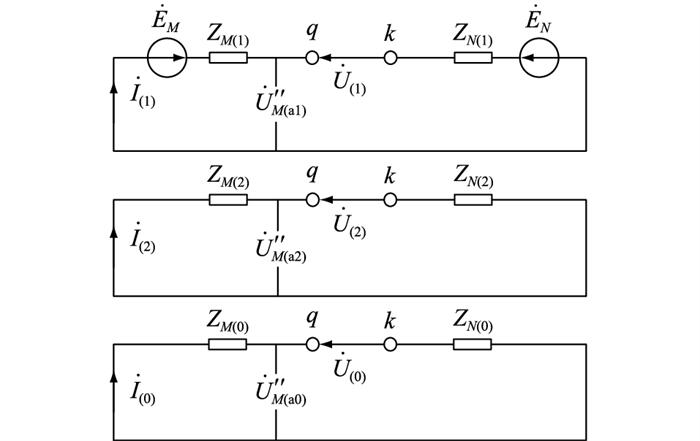
断路器跳闸后A相三序网络图如图 6所示。
|
图 6 断路器跳闸后A相三序网络图 Fig. 6 Three-sequence network diagram during circuit breaker trip of phase A |
图 6中:
| $ \left\{\begin{array}{l} \dot{U}_{q k}=\dot{U}_{(1)}+\dot{U}_{(2)}+\dot{U}_{(0)} \\ \dot{I}_{M \mathrm{a}}^{\prime \prime}=\dot{I}_{(1)}+\dot{I}_{(2)}+\dot{I}_{(0)} \end{array}\right. $ | (4) |
q, k端口的电压平衡方程式为:
| $ \left\{\begin{array}{l} \dot{U}_{q k}-\dot{I}_{(1)} Z_{(1)}=\dot{U}_{(1)} \\ 0-\dot{I}_{(2)} Z_{(2)}=\dot{U}_{(2)} \\ 0-\dot{I}_{(0)} Z_{(0)}=\dot{U}_{(0)} \end{array}\right. $ | (5) |
式中:Z(1),Z(2),Z(0)为从端口看入的等值阻抗。其计算如下:
| $ \left\{\begin{array}{l} Z_{(1)}=Z_{M(1)}+Z_{N(1)} \\ Z_{(2)}=Z_{M(2)}+Z_{N(2)} \\ Z_{(0)}=Z_{M(0)}+Z_{N(0)} \end{array}\right. $ | (6) |
故障处边界条件为:
| $ \left\{\begin{array}{l} \dot{I}_{M \mathrm{a}}^{\prime \prime}=0 \\ \dot{U}_{b b^{\prime}}=Z_{\mathrm{T}} \dot{I}_{M \mathrm{b}}^{\prime \prime} \\ \dot{U}_{c c^{\prime}}=Z_{\mathrm{T}} \dot{I}_{M \mathrm{c}}^{\prime \prime} \end{array}\right. $ | (7) |
A、B、C三相电气量关系为:
| $ \left\{\begin{array}{l} \dot{X}_{\mathrm{a}}=\dot{X}_{\mathrm{a}(1)}+\dot{X}_{\mathrm{a}(2)}+\dot{X}_{\mathrm{a}(0)} \\ \dot{X}_{\mathrm{b}}=\dot{a}^{2} \dot{X}_{\mathrm{a}(1)}+\dot{a} \dot{X}_{\mathrm{a}(2)}+\dot{X}_{\mathrm{a}(0)} \\ \dot{X}_{\mathrm{c}}=\dot{a} \dot{X}_{\mathrm{a}(1)}+\dot{a}^{2} \dot{X}_{\mathrm{a}(2)}+\dot{X}_{\mathrm{a}(0)} \end{array}\right. $ | (8) |
将式(7)转化为序分量形式并化简后为:
| $ \left\{\begin{array}{l} \dot{I}_{(1)}+\dot{I}_{(2)}+\dot{I}_{(0)}=0 \\ \dot{U}_{(1)}-Z_{\mathrm{T}(1)} \dot{I}_{(1)}=\dot{U}_{(2)}-Z_{\mathrm{T}(2)} \dot{I}_{(2)}= \\ \ \ \ \ \ \ \ \ \ \ \ \ \ \ \ \ \ \ \ \ \dot{U}_{(0)}-Z_{\mathrm{T}(0)} \dot{I}_{(0)} \end{array}\right. $ | (9) |
联立式(5)和式(9)得开路电压各序分量为:
| $ \left\{\begin{array}{l} \dot{U}_{(1)}=\frac{\dot{U}_{q k}\left[\dot{K}_{2}-Z_{(1)}\left(Z_{\Sigma(2)}+Z_{\Sigma(0)}\right)\right]}{\dot{K}_{2}} \\ \dot{U}_{(2)}=\dot{U}_{q k} Z_{(2)} Z_{\Sigma(0)} / \dot{K}_{2} \\ \dot{U}_{(0)}=\dot{U}_{q k} Z_{(0)} Z_{\Sigma(2)} / \dot{K}_{2} \end{array}\right. $ | (10) |
其中:
| $ \dot{K}_{2}=Z_{\Sigma(1)} Z_{\Sigma(2)}+Z_{\Sigma(1)} Z_{\Sigma(0)}+Z_{\Sigma(2)} Z_{\Sigma(0)} $ | (11) |
由式(10)及图 6得逆变侧换流母线处A相电压三序分量为:
| $ \left\{\begin{array}{l} \dot{U}_{M \mathrm{a}(1)}^{\prime \prime}=\frac{\dot{K}_{2} \dot{E}_{M}-Z_{M(1)} \dot{U}_{q k}\left(Z_{\Sigma(2)}+Z_{\Sigma(0)}\right)}{\dot{K}_{2}} \\ \dot{U}_{M \mathrm{a}(2)}^{\prime \prime}=\dot{U}_{q k} Z_{M(2)} Z_{\Sigma(0)} / \dot{K}_{2} \\ \dot{U}_{M \mathrm{a}(0)}^{\prime \prime}=\dot{U}_{q k} Z_{M(0)} Z_{\Sigma(2)} / \dot{K}_{2} \end{array}\right. $ | (12) |
由式(8)和式(12)可得单相断路器跳闸后换流母线电压为:
| $ \left\{\begin{array}{l} \dot{U}_{M \mathrm{a b}}^{\prime \prime}=\frac{\dot{U}_{q k} Z_{M(1)}\left[\dot{A} Z_{\Sigma(1)}+(\dot{A}-\dot{B}) Z_{\Sigma(0)}\right]-\dot{A} \dot{K}_{2} \dot{E}_{M}}{\dot{K}_{2}} \\ \dot{U}_{M \mathrm{b c}}^{\prime \prime}=\frac{(\dot{A}-\dot{B})\left[\dot{K}_{2} \dot{E}_{M}-\dot{U}_{q k} Z_{M(1)}\left(Z_{\Sigma(1)}+2 Z_{\Sigma(0)}\right)\right]}{\dot{K}_{2}} \\ \dot{U}_{M \mathrm{ca}}^{\prime \prime}=\frac{\dot{B} \dot{K}_{2} \dot{E}_{M}+\dot{U}_{q k} Z_{M(1)}\left[(\dot{A}-\dot{B}) Z_{\Sigma(0)}-\dot{B} Z_{\Sigma(1)}\right]}{\dot{K}_{2}} \end{array}\right. $ | (13) |
由式(13)可知,A相两端断路器跳闸后,逆变侧换流母线电压与系统等效参数有关,与跳闸前故障相电压及过渡电阻无关。以AB线电压为例,将式(13)中相量转变为直角坐标形式,即:
| $ \left\{\begin{array}{l} \dot{E}_{M}=m+\mathrm{j} n \\ \dot{E}_{N}=p+\mathrm{j} q \\ Z_{\mathrm{T}(1)}=r+\mathrm{j} s \\ Z_{\mathrm{T}(0)}=e+\mathrm{j} f \\ Z_{M(1)}=x+\mathrm{j} y \\ Z_{M(0)}=l+\mathrm{j} h \\ Z_{N(1)}=u+\mathrm{j} v \\ Z_{N(0)}=g+\mathrm{j} k \end{array}\right. $ | (14) |
解得A相两端断路器跳闸后,AB线电压偏移角如式(15)所示,详细推导过程见附录A。
| $ \begin{gathered} \varPhi_{\mathrm{ab}}=\theta_{\mathrm{ab}}^{\prime \prime}-\theta_{\mathrm{ab}}= \\ \arctan \frac{2(H F-E I)+(3 n+\sqrt{3} m)\left(H^{2}+I^{2}\right)}{2(H E+F I)+(3 m-\sqrt{3} n)\left(H^{2}+I^{2}\right)}-\theta_{\mathrm{ab}} \end{gathered} $ | (15) |
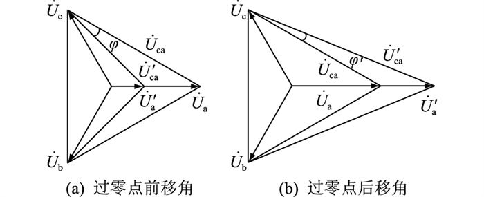
式中:Φab为偏移角,分为过零点前移角和后移角,见下述分析;θab, θ″ ab分别为断路器跳闸前、后AB线电压相位角;H, F, E, I为系统等效参数。逆变侧交流线路A相电压幅值跌落(非对称故障)及增大时,电压矢量如图 7所示。
|
图 7 偏移角 Fig. 7 Deviation angle |
图 7(a)中,A相电压幅值Ua跌落为U′ a,相位角不变;线电压
|
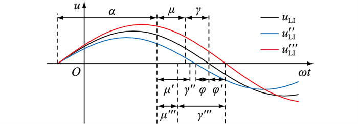
图 8 换流母线电压波形 Fig. 8 Voltage waveform of commutator bus |
图 8中,
由式(15)可知,A相断路器跳闸后,AB线电压偏移角仅与系统等效参数有关,BC及CA线电压偏移角类似。
换相失败一般发生在故障的初始阶段,考虑到PI控制的延时滞后,可认为断路器跳闸后短时间内越前触发角不变[20-21]。跳闸后,由于平波电抗器作用,直流电流在短时间内变化较小,忽略其影响[22]。在实际工程应用中,还应考虑锁相环作用,但跳闸后换流母线电压相位发生跳变,锁相环最快也需100 ms左右才能锁定电压相位,远大于换相失败发生时间,此时锁相环发挥作用较小,可忽略其影响[23-26]。将受端单回线交直流测试模型等效参数代入式(13),得断路器跳闸后各线电压如表 1所示。
|
|
表 1 断路器跳闸后线电压 Table 1 Line voltage after circuit breaker tripping |
由表 1可得A相两端断路器跳闸后换流母线电压矢量,如图 9所示。

|
图 9 换流母线电压矢量 Fig. 9 Voltage vector of commutator bus |
结合上述分析和表 1可知,断路器跳闸后
综上所述,单相断路器跳闸后引起换流母线电压过零点前移是导致关断角减小的一个重要因素。对于一个确定系统,跳闸引起的电压偏移角是确定的,与系统等效参数直接相关。
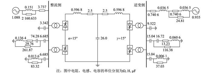
3 仿真验证文中采用PSCAD/EMTDC电磁暂态仿真软件,基于CIGRE直流标准测试模型搭建受端单回线交直流测试模型,具体参数如图 10所示[20]。
|
图 10 受端单回线交直流测试模型 Fig. 10 AC/DC test model of single circuit line at receiving end |
以γmin=7°作为换相失败判据。MN间线路长取30 km,其参数如表 2所示[14]。
|
|
表 2 交流线路参数 Table 2 AC line parameters |
|
|
表 3 等效模型参数 Table 3 Parameters of the equivalent model |
由表 3计算得
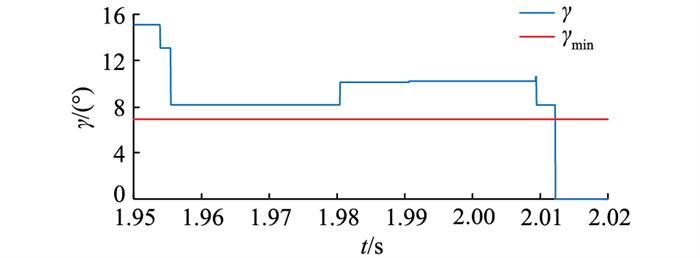
由第2章分析可知,A相两端断路器跳闸后,逆变侧换流母线电压与系统等效参数有关。断路器跳闸后,CA线电压过零点前移角过大导致γ<γmin,发生换相失败。基于受端单回线交直流测试模型仿真验证:1.95 s时逆变侧交流线路发生A相高阻接地,故障不会致使逆变器换相失败,断路器于2 s跳闸,此时Id=1.97 kA, β=41.5°,γ波形如图 11所示。图 11中A相高阻接地后,γ跌落,但并未小于γmin,没有发生换相失败。断路器于2 s跳闸隔离故障,导致系统再次受到冲击,γ再次跌落小于γmin,于2.012 s发生换相失败。
|
图 11 逆变器关断角波形(原始参数) Fig. 11 Extinction angle waveforms of inverter (original parameters) |
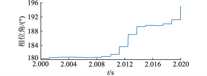
CA线电压相位角变化波形如图 12所示。其中,CA线电压相位角在换相失败后会受直流侧影响。在换相失败前可看出CA线电压相位角有增大趋势,超前于正常运行时相位角,即φ增大。仿真结果与理论分析一致。
|
图 12 CA线电压相位角波形 Fig. 12 Waveforms of phase angle of CA line voltage |
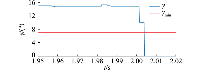
当逆变侧为无穷大系统时,γ波形如图 13所示。由图 13可知,逆变器于2.005 s换相失败。
|
图 13 逆变器关断角波形(改变交流参数) Fig. 13 Extinction angle waveforms of inverter (changing AC parameters) |
当改变直流侧系统参数时,γ波形如图 14所示。由图 14可知,γ>γmin,逆变器未发生换相失败。

|
图 14 逆变器关断角波形(改变直流参数) Fig. 14 Extinction angle waveforms of inverter (changing DC parameters) |
结合上述仿真可知,改变系统等效参数会对断路器跳闸后逆变器换相结果产生影响,验证了理论分析的正确性。
4 结语文中针对受端单回线交直流系统,基于逆变侧交流线路单相高阻接地,研究断路器跳闸对逆变器换相的影响。
(1) 推导出单相断路器跳闸后换流母线电压表达式。分析得出断路器跳闸后,换流母线电压产生较大过零点前移角,是导致逆变器关断角减小的重要因素;对于确定系统,跳闸引起的电压偏移角是确定的,与系统等效参数直接相关。
(2) 基于交直流测试模型仿真验证了理论分析的正确性:若逆变侧交流线路单相高阻接地时未发生换相失败,此时断路器跳闸会引起换流母线电压过零点前移,导致关断角减小,严重时会发生换相失败。
文中仅针对受端单回线交直流系统展开研究,后续将进一步研究受端多回线交直流系统中断路器跳闸对换相的影响以及抑制换相失败的方法。
附录A令:
| $ \left\{\begin{array}{l} \dot{E}_{M}=m+\mathrm{j} n \\ \dot{E}_{N}=p+\mathrm{j} q \\ Z_{\mathrm{T}(1)}=r+\mathrm{j} s \\ Z_{\mathrm{T}(0)}=e+\mathrm{j} f \\ Z_{M(1)}=x+\mathrm{j} y \\ Z_{M(0)}=l+\mathrm{j} h \\ Z_{N(1)}=u+\mathrm{j} v \\ Z_{N(0)}=g+\mathrm{j} k \end{array}\right. $ | (A1) |
由式(A1)得:
| $ \left\{\begin{array}{l} \dot{A}=-\frac{3}{2}-\mathrm{j} \frac{\sqrt{3}}{2} \\ \dot{B}=-\frac{3}{2}+\mathrm{j} \frac{\sqrt{3}}{2} \\ \dot{U}_{q k}=(m-p)+\mathrm{j}(n-q) \\ Z_{\Sigma(1)}=(x+u+r)+\mathrm{j}(y+v+s) \\ Z_{\Sigma(0)}=(l+g+e)+\mathrm{j}(h+k+f) \\ \dot{K}_{2}=(x+u+r)^{2}-(y+v+s)^{2}+2(x+u+r)(l+g+e)-2(y+v+s)(h+k+f)+ \\ \ \ \ \ 2 \mathrm{j}[(x+u+r)(y+v+s)+(x+u+r)(h+k+f)+(l+g+e)(y+v+s)]=H+\mathrm{j} I \end{array}\right. $ | (A2) |
以AB线电压为例,得:
| $ \begin{gathered} \dot{U}_{M \mathrm{ab}}^{\prime \prime}=\frac{\dot{U}_{q k} Z_{M(1)}\left[\dot{A} Z_{\Sigma(1)}+(\dot{A}-\dot{B}) Z_{\Sigma(0)}\right]-\dot{A} \dot{K}_{2} \dot{E}_{M}}{\dot{K}_{2}}= \\ {\left[\frac{2(H E+F I)+(3 m-\sqrt{3} n)\left(H^{2}+I^{2}\right)}{2\left(H^{2}+I^{2}\right)}\right]+\mathrm{j}\left[\frac{2(H F-E I)+(3 n+\sqrt{3} m)\left(H^{2}+I^{2}\right)}{2\left(H^{2}+I^{2}\right)}\right]} \end{gathered} $ | (A3) |
其中:
| $ \begin{gathered} \dot{U}_{q k} Z_{M(1)}\left[\dot{A} Z_{\Sigma(1)}+(\dot{A}-\dot{B}) Z_{\Sigma(0)}\right]= \\ \frac{\sqrt{3}}{2} x(m-p)(y+v+s)-\frac{3}{2} x(m-p)(x+u+r)+\sqrt{3} x(m-p)(h+k+f)- \\ \frac{\sqrt{3}}{2} y(n-q)(y+v+s)+\frac{3}{2} y(n-q)(x+u+r)-\sqrt{3} y(n-q)(h+k+f)+ \\ \frac{3}{2} x(n-q)(y+v+s)+\frac{\sqrt{3}}{2} x(n-q)(x+u+r)+\sqrt{3} x(n-q)(l+g+e)+\\ \frac{3}{2} y(m-p)(y+v+s)+\frac{\sqrt{3}}{2} y(m-p)(x+u+r)+\sqrt{3} y(m-p)(l+g+e)- \\ \frac{3}{2} \mathrm{j} x(m-p)(y+v+s)-\frac{\sqrt{3}}{2} \mathrm{j} x(m-p)(x+u+r)-\sqrt{3} \mathrm{j} x(m-p)(l+g+e)+ \\ \frac{3}{2} \mathrm{j} y(n-q)(y+v+s)+\frac{\sqrt{3}}{2} \mathrm{j} y(n-q)(x+u+r)+\sqrt{3} \mathrm{j} y(n-q)(l+g+e)+ \\ \quad \frac{\sqrt{3}}{2} \mathrm{j} x(n-q)(y+v+s)-\frac{3}{2} \mathrm{j} x(n-q)(x+u+r)+\sqrt{3} \mathrm{j} x(n-q)(h+k+f)+ \\ \frac{\sqrt{3}}{2} \mathrm{j} y(m-p)(y+v+s)-\frac{3}{2} \mathrm{j} y(m-p)(x+u+r)+\sqrt{3} \mathrm{j} y(m-p)(h+k+f)=E+\mathrm{j} F \end{gathered} $ | (A4) |
则A相断路器跳闸后AB线电压相位角为:
| $ \theta_{\mathrm{ab}}^{\prime \prime}=\arctan \frac{\frac{2(H F-E I)+(3 n+\sqrt{3} m)\left(H^{2}+I^{2}\right)}{2\left(H^{2}+I^{2}\right)}}{\frac{2(H E+F I)+(3 m-\sqrt{3} n)\left(H^{2}+I^{2}\right)}{2\left(H^{2}+I^{2}\right)}}=\arctan \frac{2(H F-E I)+(3 n+\sqrt{3} m)\left(H^{2}+I^{2}\right)}{2(H E+F I)+(3 m-\sqrt{3} n)\left(H^{2}+I^{2}\right)} $ | (A5) |
AB线电压偏移角为:
| $ \Phi_{\mathrm{ab}}=\theta_{\mathrm{ab}}^{\prime \prime}-\theta_{\mathrm{ab}}=\arctan \frac{2(H F-E I)+(3 n+\sqrt{3} m)\left(H^{2}+I^{2}\right)}{2(H E+F I)+(3 m-\sqrt{3} n)\left(H^{2}+I^{2}\right)}-\theta_{\mathrm{ab}} $ | (A6) |
式中:θab为断路器跳闸前AB线电压相位角。
| [1] |
周孝信, 陈树勇, 鲁宗相, 等. 能源转型中我国新一代电力系统的技术特征[J]. 中国电机工程学报, 2018, 38(7): 1893-1904, 2205. ZHOU Xiaoxin, CHEN Shuyong, LU Zongxiang, et al. Technology features of the new generation power system in China[J]. Proceedings of the CSEE, 2018, 38(7): 1893-1904, 2205. (  0) 0) |
| [2] |
汤奕, 郑晨一. 高压直流输电系统换相失败影响因素研究综述[J]. 中国电机工程学报, 2019, 39(2): 499-513, 647. TANG Yi, ZHENG Chenyi. Review on influencing factors of commutation failure in HVDC systems[J]. Proceedings of the CSEE, 2019, 39(2): 499-513, 647. (  0) 0) |
| [3] |
于灿平. 弱送端电网直流群同时换相失败对电网功角稳定特性的影响研究[J]. 浙江电力, 2019, 38(5): 55-61. YU Canping. Research on the stability mechanism under simultaneous commutation failure of UHVDC group in the weak sending end grid[J]. Zhejiang Electric Power, 2019, 38(5): 55-61. (  0) 0) |
| [4] |
许多, 吴峰, 史林军, 等. 基于PSCAD的特高压直流输电系统建模与仿真分析[J]. 电力工程技术, 2020, 39(3): 71-77, 98. XU Duo, WU Feng, SHI Linjun, et al. Modeling and simulation analysis of UHVDC transmission system based on PSCAD[J]. Electric Power Engineering Technology, 2020, 39(3): 71-77, 98. (  0) 0) |
| [5] |
袁阳, 卫志农, 雷霄, 等. 直流输电系统换相失败研究综述[J]. 电力自动化设备, 2013, 33(11): 140-147. YUAN Yang, WEI Zhinong, LEI Xiao, et al. Survey of commutation failures in DC transmission systems[J]. Electric Power Automation Equipment, 2013, 33(11): 140-147. DOI:10.3969/j.issn.1006-6047.2013.11.025 (  0) 0) |
| [6] |
郑传材, 黄立滨, 管霖, 等. ±800 kV特高压直流换相失败的RTDS仿真及后续控制保护特性研究[J]. 电网技术, 2011, 35(4): 14-20. ZHENG Chuancai, HUANG Libin, GUAN Lin, et al. RTDS-based simulation of commutation failure in ±800 kV DC power transmission and research on characteristics of subsequent control and protection[J]. Power System Technology, 2011, 35(4): 14-20. (  0) 0) |
| [7] |
王龙飞, 华文, 石博隆, 等. 抑制直流连续换相失败的调相机暂态强励控制策略[J]. 浙江电力, 2020, 39(8): 13-19. WANG Longfei, HUA Wen, SHI Bolong, et al. Research on transient forced excitation control strategy of synchronous condenser for continuous commutations failure mitigation[J]. Zhejiang Electric Power, 2020, 39(8): 13-19. (  0) 0) |
| [8] |
张彦涛, 邱丽萍, 施浩波, 等. 考虑不对称故障影响的多馈入直流系统换相失败快速判别方法[J]. 中国电机工程学报, 2018, 38(16): 4759-4767, 4980. ZHANG Yantao, QIU Liping, SHI Haobo, et al. Fast detection method of commutation failure in multi infeed DC system considering the effect of unbalanced fault[J]. Proceedings of the CSEE, 2018, 38(16): 4759-4767, 4980. (  0) 0) |
| [9] |
王峰, 刘天琪, 李兴源, 等. 考虑直流电流上升及交流电压下降速度的换相失败分析[J]. 电力系统自动化, 2016, 40(22): 111-117. WANG Feng, LIU Tianqi, LI Xingyuan, et al. Commutation failure analysis considering DC current rise and AC voltage drop speed[J]. Automation of Electric Power Systems, 2016, 40(22): 111-117. DOI:10.7500/AEPS20151020007 (  0) 0) |
| [10] |
李兴源. 高压直流输电系统[M]. 北京: 科学出版社, 2010. LI Xingyuan. High voltage direct current transmission systems[M]. Beijing: Science Press, 2010. (  0) 0) |
| [11] |
王智冬. 交流系统故障对特高压直流输电换相失败的影响[J]. 电力自动化设备, 2009, 29(5): 25-29, 38. WANG Zhidong. Impact of AC system fault on UHVDC commutation failure[J]. Electric Power Automation Equipment, 2009, 29(5): 25-29, 38. DOI:10.3969/j.issn.1006-6047.2009.05.005 (  0) 0) |
| [12] |
徐敬友, 谭海燕, 孙海顺, 等. 考虑直流电流变化及交流故障发生时刻影响的HVDC换相失败分析方法[J]. 电网技术, 2015, 39(5): 1261-1267. XU Jingyou, TAN Haiyan, SUN Haishun, et al. Research on method to analyze commutation failure in HVDC power transmission system considering the impact of DC current variation and occurrence moment of AC fault[J]. Power System Technology, 2015, 39(5): 1261-1267. (  0) 0) |
| [13] |
刘济豪, 郭春义, 刘文静, 等. 基于改进换相面积的直流输电换相失败判别方法[J]. 华北电力大学学报(自然科学版), 2014, 41(1): 15-21. LIU Jihao, GUO Chunyi, LIU Wenjing, et al. Commutation failure detective method based on improved commutation area in HVDC[J]. Journal of North China Electric Power University (Natural Science Edition), 2014, 41(1): 15-21. DOI:10.3969/j.ISSN.1007-2691.2014.01.03 (  0) 0) |
| [14] |
胡涛, 朱艺颖, 印永华, 等. 含多回物理直流仿真装置的大电网数模混合仿真建模及研究[J]. 中国电机工程学报, 2012, 32(7): 68-75, 193. HU Tao, ZHU Yiying, YIN Yonghua, et al. Modeling and study of digital/analog hybrid simulation for bulk grid with multi-analog HVDC simulators[J]. Proceedings of the CSEE, 2012, 32(7): 68-75, 193. (  0) 0) |
| [15] |
邓俊, 苏懿, 刘坤雄, 等. 基于频率特性的交直流系统次同步振荡分析[J]. 电网技术, 2018, 42(12): 3857-3863. DENG Jun, SU Yi, LIU Kunxiong, et al. Analysis of sub-synchronous oscillation of AC/DC system based on frequency characteristics[J]. Power System Technology, 2018, 42(12): 3857-3863. (  0) 0) |
| [16] |
陈仕龙, 束洪春, 甄颖. 云广特高压直流输电负极运行换相失败及控制研究[J]. 电力自动化设备, 2013, 33(6): 128-133. CHEN Shilong, SHU Hongchun, ZHEN Ying. Commutation failure of Yun-Guang UHVDC transmission system running in negative pole state and its control measures[J]. Electric Power Automation Equipment, 2013, 33(6): 128-133. DOI:10.3969/j.issn.1006-6047.2013.06.024 (  0) 0) |
| [17] |
罗隆福, 周金萍, 李勇, 等. HVDC换相失败典型暂态响应特性及其抑制措施[J]. 电力自动化设备, 2008, 28(4): 5-9, 36. LUO Longfu, ZHOU Jinping, LI Yong, et al. Typical transient response of HVDC commutation failure and its countermeasures[J]. Electric Power Automation Equipment, 2008, 28(4): 5-9, 36. DOI:10.3969/j.issn.1006-6047.2008.04.002 (  0) 0) |
| [18] |
王晨清, 宋国兵, 汤海雁, 等. 选相及方向元件在风电接入系统中的适应性分析[J]. 电力系统自动化, 2016, 40(1): 89-95. WANG Chenqing, SONG Guobing, TANG Haiyan, et al. Adaptability analysis of phase selectors and directional relays in power systems integrated with wind farms[J]. Automation of Electric Power Systems, 2016, 40(1): 89-95. (  0) 0) |
| [19] |
陈实, 邰能灵, 范春菊, 等. 逆变型电源接入对选相元件的影响分析[J]. 电力系统自动化, 2017, 41(12): 106-112, 187. CHEN Shi, TAI Nengling, FAN Chunju, et al. Influence of inverter-interfaced generator on element of phase selectors[J]. Automation of Electric Power Systems, 2017, 41(12): 106-112, 187. (  0) 0) |
| [20] |
尹纯亚, 李凤婷, 宋新甫, 等. 多馈出直流系统换相失败快速判别方法[J]. 电网技术, 2019, 43(10): 3459-3465. YIN Chunya, LI Fengting, SONG Xinfu, et al. A fast detection method of commutation failure in multi-outfeed DC system[J]. Power System Technology, 2019, 43(10): 3459-3465. (  0) 0) |
| [21] |
饶宇飞, 张鹏辉, 李程昊, 等. 励磁涌流对高压直流输电系统换相失败的影响机理及评估方法[J]. 电力系统保护与控制, 2019, 47(13): 54-61. RAO Yufei, ZHANG Penghui, LI Chenghao, et al. Mechanism and evaluating method for HVDC commutation failure caused by inrush current[J]. Power System Protection and Control, 2019, 47(13): 54-61. (  0) 0) |
| [22] |
刘俊磊, 王钢, 李海锋, 等. HVDC系统换相失败对交流电网继电保护影响的机理分析[J]. 中国电机工程学报, 2013, 33(19): 111-118, 13. LIU Junlei, WANG Gang, LI Haifeng, et al. Mechanism analy-sis of HVDC commutation failure influence on AC power network relay protection[J]. Proceedings of the CSEE, 2013, 33(19): 111-118, 13. (  0) 0) |
| [23] |
龚英明, 汪娟娟, 王子民, 等. 一种应用于高压直流输电的新型锁相环[J]. 电网技术, 2019, 43(11): 4097-4104. GONG Yingming, WANG Juanjuan, WANG Zimin, et al. A novel phase-locked loop for HVDC[J]. Power System Technology, 2019, 43(11): 4097-4104. (  0) 0) |
| [24] |
李子林, 傅闯, 汪娟娟, 等. 实现相位和频率检测解耦的快速锁相环[J]. 电力系统自动化, 2019, 43(5): 143-151. LI Zilin, FU Chuang, WANG Juanjuan, et al. Fast phase-locked loop to realize decoupled detection of phase and frequency[J]. Automation of Electric Power Systems, 2019, 43(5): 143-151. (  0) 0) |
| [25] |
王佳浩, 潘欢, 纳春宁. 电网电压不平衡和谐波畸变下新型并网锁相环设计[J]. 电力系统保护与控制, 2019, 47(15): 108-115. WANG Jiahao, PAN Huan, NA Chunning. A new grid-connected phase-locked loop design under grid voltage imbalance and harmonic distortion conditions[J]. Power System Protection and Control, 2019, 47(15): 108-115. (  0) 0) |
| [26] |
王子民, 汪娟娟, 傅闯, 等. 基于单相锁相环的高压直流分相触发相位控制[J]. 电力系统自动化, 2018, 42(21): 160-165. WANG Zimin, WANG Juanjuan, FU Chuang, et al. Individual phase control of high voltage direct current based on single-phase locked loop[J]. Automation of Electric Power Systems, 2018, 42(21): 160-165. (  0) 0) |
2. Engineering Research Center for Renewable Energy Power Generation and Grid Technology (Xinjiang University), Ministry of Education, Urumqi 830047, China
 2022, Vol. 41


 宋新甫(1983), 男, 硕士, 高级工程师, 从事电力系统运行控制工作(E-mail: